


Expanding an audio setup often leads to practical wiring questions, especially when an amplifier or receiver has fewer speaker outputs than the total number of drivers you want to power. Many listeners wonder, can i connect 2 speakers to 1 channel without damaging their equipment or losing clear audio quality. The short answer is yes, but doing so safely depends entirely on understanding electrical impedance, power handling, and proper circuit wiring. Whether you are adding background sound across a living room or upgrading traditional stereo loudspeakers, connecting multiple speakers to a single terminal requires careful matching.
If you attach two speakers incorrectly, you risk overheating your receiver or triggering built-in protection circuits that shut down playback entirely. Parallel wiring cuts overall electrical resistance in half, which can strain amplifiers that cannot handle low-impedance loads, whereas series wiring increases resistance and limits available volume. Using specialized hardware, such as an impedance-matching selector box or a line output converter for multi-component systems, can protect your gear while keeping sound balanced. Checking your amplifier specifications before twisting wires together remains the most critical step for avoiding costly hardware failures.


Technical Guide to Wiring Multiple Speakers to a Single Channel
Connecting multiple speakers to a single amplifier terminal is a routine task in audio setups, but doing so without evaluating electrical specifications can quickly cause hardware problems. Physical wire connections are simple enough because copper leads can be spliced, twisted, or linked in sequence. However, every driver attached to a channel fundamentally alters the electrical resistance that the amplifier must drive. Knowing how to calculate that combined resistance and selecting the appropriate circuit path prevents distorted sound, unwanted overheating, and permanent damage to your equipment.
The Core Rule of Speaker Impedance and Amplifier Loads
Impedance represents the electrical resistance a speaker opposes to the alternating current signal delivered by an amplifier, measured in ohms. Most home audio speakers carry a nominal rating of four, six, or eight ohms, though dynamic impedance fluctuates depending on the played frequency. Amplifiers are engineered to operate stably within a specified impedance range, typically printed on the back panel near the terminal binding posts. Forcing an amplifier to drive a load below its rated minimum demands excessive current, which rapidly generates heat.
When an amplifier encounters a load that is too low, the output transistors must work significantly harder to supply current. This extra electrical strain causes internal heat sinks to warm up rapidly, often engaging thermal protection relays in modern receivers. In older or budget equipment without protective circuitry, driving an unsafe load can burn out output stages or blow internal fuses. Conversely, connecting a higher impedance load is electrically safe for the amplifier, even though it reduces the maximum volume output.
Checking the minimum impedance rating on your amplifier or stereo receiver is always the mandatory first step before stripping any speaker wire. If your amplifier states a minimum load of four ohms, you can safely connect multiple speakers as long as their combined electrical load does not fall below four ohms. If your amplifier requires an eight-ohm minimum, connecting two four-ohm speakers directly in parallel will drop the load to two ohms, creating an immediate overload risk. Taking a few moments to inspect the specifications printed on your components protects your entire investment.
Parallel Wiring: Calculations, Output, and Thermal Risks
Parallel wiring is the most common method people choose when connecting multiple speakers to one channel because it is simple to assemble. In a parallel circuit, the positive terminal of the amplifier connects directly to the positive terminals of both speakers, and the negative terminal connects to both negative terminals. This configuration ensures that both speakers receive the exact same audio signal and voltage output from the source. The major trade-off is that wiring in parallel cuts the total impedance seen by the amplifier in half when using identical speakers.
The mathematical formula for parallel impedance divides the product of the two resistances by their sum. When you connect two identical eight-ohm speakers in parallel, the amplifier sees an easy four-ohm load, which most modern home amplifiers can handle comfortably. However, if you wire two four-ohm speakers in parallel, the total load drops to a dangerously low two ohms. Unless you possess a specialized, two-ohm-stable power amplifier, running a two-ohm load will lead to rapid thermal overload and harsh audio distortion.
Parallel wiring delivers the advantage of maintaining full acoustic output and equal volume across both drivers, assuming identical sensitivity ratings. Because each speaker receives the full signal voltage directly from the amplifier, neither driver compromises the frequency response of the other. The primary hazard remains amplifier overheating during extended listening sessions at moderate to high volumes. Anyone using parallel connections should monitor the chassis temperature of their receiver during initial use to confirm that cooling airflow remains sufficient.
Series Wiring: Resistance Benefits and Acoustic Trade-Offs
Series wiring provides an electrically safe alternative when you need to power two low-impedance speakers from an amplifier that cannot handle low resistance loads. In a series circuit, audio current flows through one speaker before passing into the next one in a single continuous loop. To wire two speakers in series, connect the amplifier positive terminal to the positive terminal of the first speaker. Then, run a jumper wire from the negative terminal of the first speaker to the positive terminal of the second speaker, and finally connect the second speaker negative terminal back to the amplifier negative terminal.
The total impedance in a series circuit is simply the sum of each individual speaker impedance. Connecting two four-ohm speakers in series creates an eight-ohm load, which is completely safe for virtually any consumer audio receiver on the market. If you wire two eight-ohm speakers in series, the amplifier encounters a sixteen-ohm load, eliminating any possibility of electrical strain. The clear safety advantage makes series wiring a reliable choice for background music systems where high volume is unnecessary.
Despite its electrical safety, series wiring introduces notable acoustic drawbacks that critical listeners usually prefer to avoid. Doubling the impedance cuts the power output delivered by the amplifier, resulting in noticeably lower overall sound levels for a given volume setting. Furthermore, connecting voice coils in series allows the mechanical motion of one driver to generate back electromotive force that can alter the frequency response of the second driver. This interaction degrades the damping factor of the amplifier, leading to looser, less precise bass reproduction.
Series-Parallel Networks for Four or More Drivers
When an audio setup requires connecting four speakers to a single channel or a stereo pair, a series-parallel network offers an ideal balance of safety and power. This technique combines the resistance-increasing effect of series connections with the resistance-lowering effect of parallel connections. By grouping drivers into pairs, you can wire each pair in series and then connect those two pairs together in parallel across the amplifier channel. The resulting combination allows you to power multiple drivers while preserving safe electrical boundaries.
Calculating the final load of a series-parallel network demonstrates why commercial installers frequently rely on this wiring arrangement. For instance, four identical eight-ohm speakers wired in two series pairs create two separate sixteen-ohm loads. When those two sixteen-ohm groups are subsequently connected in parallel to the amplifier, the resulting overall load returns precisely to eight ohms. This allows an amplifier to drive four separate physical speakers while operating within its optimal, factory-rated eight-ohm operating zone.
Implementing a series-parallel circuit requires careful wire management and methodical labeling to prevent phase cancellation or incorrect terminal routing. Using color-coded speaker wire helps you track the path of each conductor between the different speaker enclosures. If one speaker in the network is wired out of phase, bass response will drop sharply, making the entire setup sound thin and hollow. Testing each branch systematically ensures that all drivers move in unison and maintain proper acoustic energy.
Using Dedicated Speaker Switchers and Selector Boxes
Installing a dedicated hardware switching unit is often far superior to manually twisting multiple bare wires into a single amplifier terminal. A well-designed accessory, such as the A ADWITS 2-Channel Speaker Switcher Selector Box, allows you to distribute audio signals cleanly across multiple pairs of speakers. These selector boxes feature push-button controls and secure terminal clamps, making it simple to activate individual speaker pairs or play them simultaneously. They eliminate messy wire tangles behind your equipment rack and provide reliable physical connections.
Quality speaker selectors often incorporate internal impedance-protection circuitry, such as heavy-duty resistor networks, to protect your amplifier from dangerous load drops. When multiple speaker zones are switched on at the same time, the internal circuitry prevents the net impedance from falling below safe amplifier limits. The ADWITS switcher handles up to 150W RMS per channel, making it well-suited for typical home stereo receivers and multiroom background audio. Using a purpose-built switcher prevents accidental short circuits that can occur when several thick wire strands compete for space inside one spring clip.
Beyond safety, selector boxes provide unmatched convenience for managing different listening areas throughout a home or workspace. You can direct music to the living room, switch output to an adjacent patio, or activate both zones during social gatherings without altering receiver settings. The clean mechanical switches isolate channels properly, preventing signal crosstalk and maintaining balanced stereo imaging. For anyone planning a permanent multi-speaker installation from a single receiver, a dedicated selector box remains the cleanest and most dependable hardware solution.
Car Audio Systems and Line-Level Signal Adapters
Vehicle audio systems present unique challenges when attempting to run multiple speakers off a single factory head unit channel. Standard automotive head units usually feature integrated amplifier chips designed to drive four-ohm or two-ohm factory drivers with modest power. Splicing extra speakers directly into factory door speaker wires quickly causes the small internal amplifier to overheat, distort, or clip aggressively. If you plan to add extra sound reproduction in a vehicle, upgrading to aftermarket component speakers with external amplification delivers significantly better clarity and safety.
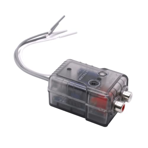
To integrate additional speakers or subwoofers without overloading factory wiring, audio installers rely on specialized signal adapters. Hardware like the FSLPQP 2-Channel High to Low Converter taps into factory speaker lines and steps down the high-voltage speaker signal into a clean, low-voltage RCA pre-amp signal. This line output converter enables you to feed an external multi-channel power amplifier without cutting factory harnesses or stressing the head unit. The external amplifier can then effortlessly power multiple drivers, subwoofers, or distinct audio zones with dedicated power rails.
In addition to component drivers, many vehicle owners install compact coaxial speakers in dash or rear deck locations to enhance high-frequency presence. If an owner attempts to parallel two coaxial speakers onto one head unit output, the combined impedance can drop below two ohms, causing the head unit to mute unexpectedly. Using another FSLPQP 2 Channel High to Low RCA Converter Car allows proper integration of an aftermarket amplifier dedicated to driving those extra coaxial units. Dedicated amplification preserves signal integrity, eliminates head unit thermal stress, and provides adjustable gain matching for balanced sound.
Power Distribution, Sensitivity, and Driver Matching
Connecting two speakers to one channel fundamentally divides the available amplifier power between those two drivers. In a parallel circuit, both speakers see the same voltage, meaning that each speaker draws current based on its individual impedance rating. If you connect two identical eight-ohm speakers to a channel capable of delivering 100 watts into a four-ohm load, each speaker receives approximately 50 watts of clean power. However, if the speakers have different impedance ratings, power will not divide equally, causing the lower-impedance speaker to draw more current and play louder.
Driver sensitivity plays an equally critical role in determining how balanced your multi-speaker system sounds in practice. Speaker sensitivity is typically measured in decibels produced from one watt of input at a distance of one meter. If one speaker has a sensitivity rating of 86 dB and the second speaker is rated at 92 dB, the second speaker will sound nearly twice as loud even when receiving the exact same amount of wattage. To maintain balanced sound coverage across both listening locations, always aim to pair speakers that feature identical or very similar sensitivity specifications.
Mismatched frequency response can also create strange tonal anomalies when two different speaker models share a single channel. A full-range bookshelf speaker wired in parallel with a small satellite driver can create uneven phase interactions across the midrange frequencies. These phase cancellations make vocals sound hollow and reduce the precision of the stereo soundstage. Whenever possible, pair identical speaker models with identical driver configurations to ensure seamless acoustic blending and predictable power distribution.
Step-by-Step Instructions for Connecting Two Speakers
Before handling any audio cables, turn off the power to your amplifier or receiver and disconnect it from the electrical wall outlet. Working with live speaker terminals risks accidental short circuits if stray copper strands touch the chassis or adjacent binding posts. Gather your speaker wire, a dependable wire stripper, and electrical tape or heat-shrink tubing if you plan to make inline splices. Inspect the back panel of your amplifier to confirm its rated minimum impedance before selecting your wiring configuration.
Strip approximately half an inch of protective insulation from the ends of each speaker wire, ensuring that you do not nick or cut the internal copper strands. Tightly twist the exposed copper strands clockwise so that no stray wire hairs can splay out and contact adjacent metal surfaces. If you are wiring in parallel at the amplifier, twist the positive conductors from both speakers together into a single tight bundle, and do the same for the negative conductors. If your amplifier binding posts accommodate banana plugs, using dual banana connectors makes this combined connection much cleaner and more secure.
For series wiring, route the positive lead of the first speaker to the positive output terminal on your amplifier. Connect the negative terminal of the first speaker to the positive terminal of the second speaker using an insulated jumper cable. Finally, run the negative lead of the second speaker directly back to the negative output terminal of the amplifier. Double-check all terminal connections to verify that positive terminals consistently connect to positive terminals and negative terminals connect to negative terminals across every junction.
Once all wires are securely fastened, reconnect power to your amplifier and set the master volume to its lowest setting. Begin playback of a familiar audio track and slowly raise the volume to a modest listening level while listening closely for clarity. Place your hand near the amplifier cooling vents after fifteen minutes of playback to verify that the chassis remains within a normal operating temperature. If the sound remains crisp and the amplifier stays cool, your multi-speaker connection is functioning safely.
Warning Signs of an Overloaded Amplifier Channel
Recognizing early warning signs of an overloaded amplifier channel allows you to correct wiring mistakes before permanent hardware damage occurs. The most obvious indicator is an amplifier that repeatedly clicks into protection mode and shuts down sound output. Modern receivers feature sensitive protection relays that monitor output current, instantly cutting speaker output when electrical resistance drops too low. If your receiver powers off or displays a protect message during loud musical passages, your combined speaker impedance is almost certainly below the safe threshold.
Severe acoustic distortion at moderate listening levels serves as another clear symptom of an overburdened output stage. When an amplifier struggles to deliver sufficient current into a low-impedance load, the audio waveform flattens, causing harsh harmonic clipping. This clipping sounds like scratching, buzzing, or static, especially during heavy bass beats or dynamic orchestral crescendos. Extended clipping sends excessive high-frequency energy to tweeters, which can quickly overheat and destroy delicate voice coils.
Unusual heat buildup on the exterior casing of your audio receiver provides a physical warning that the internal power supply is working beyond its intended limits. While all amplifiers generate some warmth during operation, the chassis should never become hot to the touch during normal listening. If you notice an acrid electrical odor or hear a faint buzzing hum radiating from the amplifier power transformer, disconnect the speakers immediately. Re-evaluate your total circuit impedance, check for frayed wire shorts, and consider switching from parallel to series wiring or using an impedance-matching selector.
Essential Best Practices for Reliable Performance
Connecting two speakers to a single channel is entirely feasible when you respect the electrical limitations of your audio components. Always verify the nominal impedance of each speaker and calculate the combined load before making permanent connections to your amplifier. If your equipment supports a four-ohm load, parallel wiring offers the cleanest sound output and simplest wiring path for a pair of standard eight-ohm speakers. When dealing with lower impedance speakers or sensitive receivers, series wiring or dedicated speaker selector boxes provide essential protection against equipment failure.
For vehicle installations or multiroom home audio where simple series or parallel connections fall short, investing in proper interface hardware is the smartest choice. High-to-low line output converters make it easy to route audio from factory channels into robust aftermarket amplifiers, preserving sound clarity and vehicle reliability. Taking the time to match driver sensitivities, maintain consistent polarity, and monitor amplifier operating temperatures ensures that your multi-speaker audio system provides clear, dynamic sound for years to come.






Write Your Review
No reviews yet. Be the first to share your experience!